Do you still have any doubt about the effect of QoS on the Switch of TP-Link?
Nowadays, the function of QoS (Quality of Serves) is being used widely in the WAN and LAN. Some companies use the function to make sure the sensitive stream can get high priority. For VoIP to be a realistic replacement for standard public switched telephone network (PSTN) telephony services, customers need to receive the same quality of voice transmission they receive with basic telephone services—meaning consistently high-quality voice transmissions. However,some customer may still have doubt about the effect of QoS, this article will show that what the QoS can really do in a professional way.
Precondition:
Here is a key point which should be known before we have the experiment that: the function of QoS only works when the network congestion happens. So it’s the first step to make network congestion happen. However, since it is hard for us to create a network congestion manually, it’s necessary to use some professional test equipment. Here we take the Spirent Test Center as an example to make the congestion and verify the effect of QoS in TP-LINK Switch.
Topology:
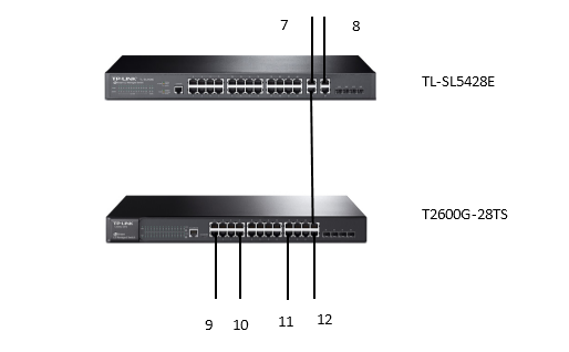
Equipment: TL-SL5428E; T2600-28TS; Spirent Test Center
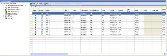
Topology Introduction: Test Center have six lines, we can see them as six different clients. Two of them, line 7 and line 8, were used to be the senders, while the rest of them, line 9 to line 12, were used to be the receivers. Obviously, if both the line 7 and 8 send data with the speed of 1000Mbps (the one-way speed), it will cause network congestion at the uplink port we used in the topology. Because the uplink port is also a Gigabit port. What’s more, before we start the test, there is one thing we must do. We know that if the WRR Mode works, the four queues TC0-TC3 will show a proportion of 1:2:4:8(refer to the User Guide of TL-SL5428E), so to make it is possible, we should create special data streams. Here is a way: Sender 7 will divide its data stream to three parts, and send them to 9/10/11. While sender 8 also divide its data stream to three parts, and send them to 11/12/12. The result is line 9/10/11/12 can get 1/3; 1/3; 2/3; 2/3 respectively. Till now, we are ready to see the differences what the configuration of QoS in the TL-SL5428E can make.
Step 1:
Configure the function of QoS in TL-SG5428E.
QoS --- DiffServ ---802.1P/CoS mapping
Enable the 802.1P Priority, and keep the mapping as default. Then go to Schedule Mode, choose one of them, SP Mode, WRR Mode, SP+WRR Mode, EQU Mode. Here we choose WRR Mode as an example, which means if the QoS does work, we will see the data with four different priorities 0,2,4,6 can show a proportion of 2:1:4:8.

Step 2:
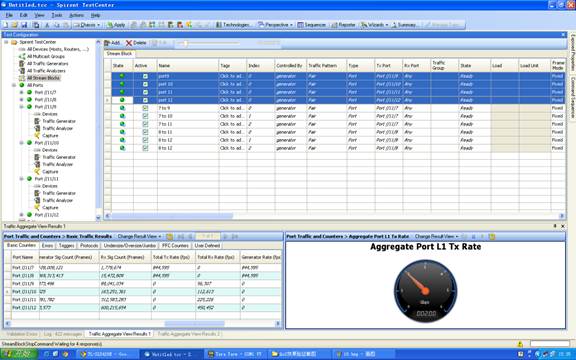
Create data streams according to what we define in the Topology Introduction.
Step 3:
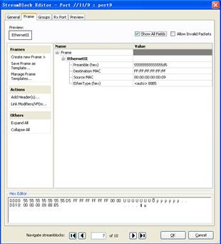
To make the port know the MAC Address of others, we should give them an opportunity to learn. So we create a broadcast packet for 9/10/11/12 ports.
Step 4:
After we create the rule of data stream’s direction, we should give the data some different priority. There are six stream, 7 to 9; 7 to 10; 7 to 11; 8 to 11; 8 to 12; 8 to 12. We should configure the Destination MAC and Source MAC. What’s more, a VLAN tag is necessary. The Priority must be set as we designed before to match the mapping in the switch.
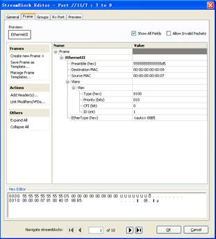
7 to 9
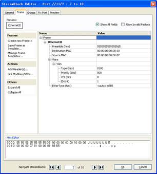
7 to 10
Step 5:
Click “All Stream Blocks”, then choose them all, click “Start”.
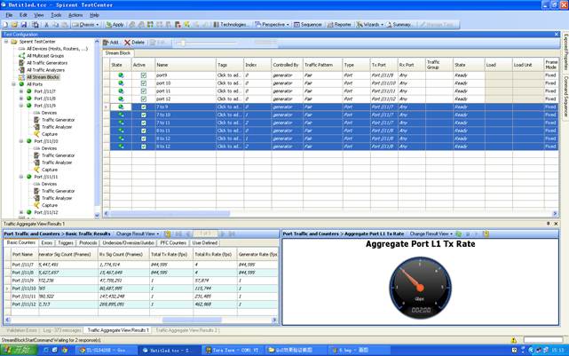
You can see the result above. As the Print Screen shows, the figure in the red frame conform to the proportion of 1:2:4:8, which means the WRR Mode does work.
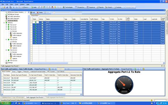
With the same step we can test SP Mode.
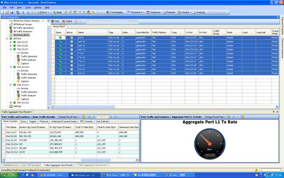
The same step we can test EQU Mode.
Step 6:
The experiment above can be an evidence that our QoS of 802.1p does work. Then we can still have a test about the DSPC Priority. Create data packet again, for this time, we need create an IP packet. Edit the stream, click the ToS/DiffServ. Then, fill in a DSCP value. According to the mapping of Queue and DSCP, here we set 7; 18; 46; 56 for test. Do the operation in step 5 again.
Esta FAQ é útil?
Seu feedback ajuda a melhorar este site.


3.2_normal_1594974261923z.png)
