How to configure LACP on our Smart/ Managed Switch
Introduction
LAG is short for link aggregation group, including static LAG and LACP(Link Aggregation Control Protocol) two achievement mechanisms. LACP, defined in IEEE802.3ad, is used to combine multiple physical links dynamically as a logical link, and thus this logical link will have higher bandwidth and higher reliability. Here we take an example to clarify how to configure LACP feature between two TP-Link switches.
Application Scenario
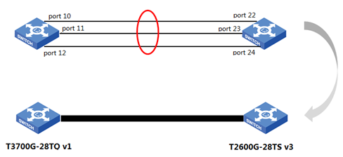
As shown in the picture below, here are T3700G-28TQ v1 and T2600G-28TS v3. We want to aggregate port 10, 11, 12 of T3700G-28TQ and port 22, 23, 24 of T2600G-28TS via LACP protocol.

Configuration Process
Before everything, at the first place we cannot connect the two switches through three cables at the same time because it will make broadcast storm if there is no advanced configuration like LAG.
For T3700G-28TQ:
Go to Switching-----LAG----LACP Config as screenshots below. Check port 10, 11, 12, designate an Admin Key 2 for these ports. The ports with the same Admin Key will be aggregated to the same group. Leave the port priority as default. Then Choose Mode as Active and Status as Enable. And click Apply to take settings into effect.

Ps.
1. A lower system priority value indicates a higher system priority. When exchanging information between systems, the system with higher priority determines which link aggregation a port belongs to, and the system with lower priority adds the proper ports to the link aggregation according to the selection of its partner. If the System Priority value is the same, the device with smaller MAC address owns higher priority.
2. There are two modes of ports: Active and Passive. In Active mode, the port can send LACP packets actively while in Passive mode, the port can only send LACP packets after it has received a LACP packet. It is suggested that set one side as Active mode and the other side as Passive mode.
For T2600G-28TS:
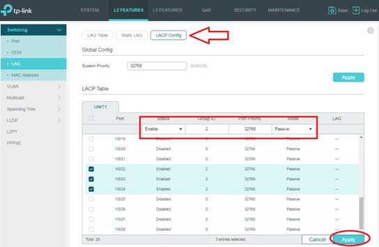
The configuration process is basically the same as above. On the main Web page, go to L2 FEATURES---->Switching---->LAG---->LACP Config. Check port 22, 23, 24. And modify status as Enable, Group ID as 2, Port Priority as 32768, Mode as Passive. Then click Apply.

We’ve finished the whole configuration process. And now we should connect the two switches’ corresponding ports with three cables.
Results
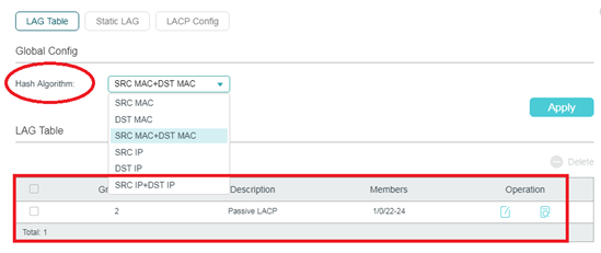
We can check the results in the LAG Table. Since the lines are aggregated or disaggregated dynamically into the group, when we connect three corresponding ports, 22-24 port will become member ports of LAG2 for T2600G-28TS. It indicates LACP feature takes effect.

In the Global Config page there is Hash Algorithm setting. We normally keep it as default as SRC MAC+DST MAC. When packets are forwarding to a LAG, switch performs Hash Algorithm operation on source and destination MAC address of each packet and according to calculation results selects corresponding port for data forwarding.
Note:
We strongly recommend you should firstly configure LAG feature on switch before other functions like VLAN, STP, QoS, GVRP, port attributes, MAC Address Learning mode and other associated settings. The LAG group is a logical link, and LAG’s configuration for these features has a higher priority than configuration for ports that LAG includes.
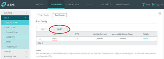
Get back to example we mentioned above. After finishing configuration of LACP feature, there will form a LAG2 for T2600G-28TS v3. And LAG2 includes port 22, 23, 24 as member ports. Let’s try to find where to configure LAG2’s VLAN PVID. Go to L2 FEATURES--->VLAN--->802.1Q VLAN--->Port Config. There are two columns UNIT1 and LAG as shown below. On UNIT1 we could configure port 22, 23, 24. And on LAGS we could configure LAG2. Since port 22, 23, 24 belong to LAG2, LAG2’s configuration has a higher priority than port 22, 23, 24. We should Click LAGS and configure PVID of LAG2.

¿Es útil esta pregunta frecuente?
Sus comentarios nos ayudan a mejorar este sitio.


1.0_01-Omada-pro-switch_normal_20231016055556b.png)

